
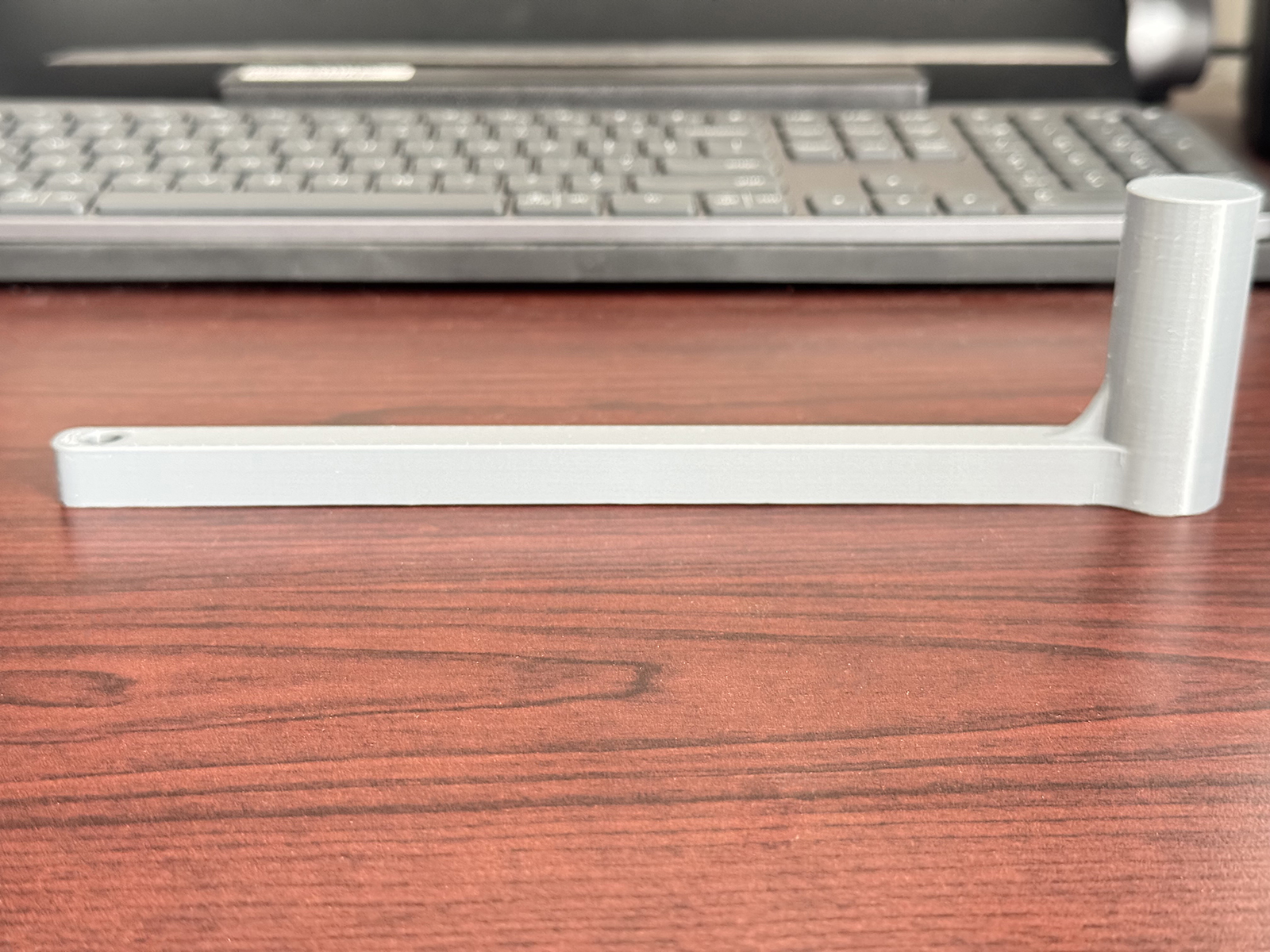
I designed this 3D printed Linn Tonearm Alignment Tool to the exact manufacturer specifications of the original metal Kinky Arm Alignment Tool. My dad is a vintage stereo equipment enthusiast, and after he bought a Linn Sondek LP-12 turntable, he asked me to create this tool for him.
Linn originally made their tool from machined aluminum, but they no longer sell it individually and recreations can cost nearly $100 USD. This seemed like the perfect candidate for a less expensive 3D printable version; for a single-use tool, even the most loyal audiophiles can’t often justify that price.
For such a simple tool, though, it proved to be quite the design challenge. I learned a lot about PLA plastic’s thermal properties and the mechanical aspects of 3D printing in general.

Finding the dimensions

The first step was finding the dimensions of the original Linn tonearm alignment tool. If my design wasn’t an exact match, I couldn’t promise that it would be an effective replacement.
My dad was able to dig up the radial specification on one forum, and other dimensions on another forum thread. The second set of dimensions was for recreating the original tool out of two pieces of bar stock with a bolt connecting them. After looking at it for a bit, I decided to make it a single-piece design for simplicity and ease of printing.
Design challenges
The design itself was fairly simple, but I ran into several unexpected and interesting challenges along the way.

Layer line bulge
Many 3D printers are plagued by this particular problem, even today. Some model files are more prone to it than others. In this case, the top layer of the handle was causing a corresponding bulge through the cylinder. It didn’t affect the functionality, but I don’t like how it looks so I chose to re-tune my printer settings.
Adhesion issues also compounded the bulge. The base of the cylinder often lifted up from the print plate during printing, causing the layers to stack too tightly and “squish” a bit like pressing down on the top of a burger bun. The toppings and sauces – or plastic, in this case – ooze out the size and make a mess. I solved this by using a brim all the way around the tool to really keep it stuck down during printing.

Pockmarks
These pockmarks or “zits” appear every time the print nozzle stops and starts a layer. 3D printing isn’t done in one continuous path; the nozzle needs to stop, lift, and move to a new part of the print to start the next layer. This often leaves little gaps that appear like pockmarks. With objects with sharp corners, you can hide the layer seams, but with circular objects like this, it’s a bit harder.
I chose to set the seams to fully aligned vertically, so that while it would have a noticeable “zipper” running up one part of the cylinder, it would look a bit cleaner than random zits.
This became less of a problem as I upgraded my 3D printers from the Prusa Mk3S+ to the Prusa Mk4 and now the Prusa CoreONE. As the printers evolve, so does their software, and gradually the default seam settings gave me cleaner results.

Angle problems
The first few prototypes of the tool weren’t quite square where the cylinder meets the arm, partially due to the adhesion issues I mentioned before. Adding a thin triangular fin between the two parts helped immensely, stabilizing the part both during printing and during use. I made sure not to make it too tall, though, since that would interfere with how the cylinder fits into the tonearm’s collar during use.
It didn’t completely eliminate the angle issues, however. I had to tweak the printing settings for that by reducing the printer’s speed during that part of the print. Slower speeds meant more stable layers, which greatly improved dimensional accuracy.

Layer shifts
Honestly, this one still happens on occasion… one of the quirks of 3D printers that use ribbed belts to move the extruder head. This tool in particular had issues with it due to its geometry. Occasionally the extruder’s nozzle would catch on burrs left on the top surface of the handle. This knocked it out of register ever so slightly, and layer shifts became more noticeable.
The solution here was to slow the printing speed down for this layer, and to dial back the amount of plastic the printer extruded. That reduced the risk of shifting as well as reduced the burrs left behind on that top layer.

Text placement – on the print plate
My first thought for adding my branding information to the final product was to make it the most visible when the tool is in use. This meant debossing it into the surface that sits against the print plate while it’s being 3D printed.
I wasn’t really happy with how the text looked; the outlines around the letters were more visually prominent than I wanted, and some of the details of the letters got blurred. It also meant that if any of the little dots or triangles inside the letters didn’t stick to the print plate, the entire print could fail after that. I ended up moving the text to another surface instead.

Text placement – against the platter
The next most logical place was to put the text on the top of the tool while printing, or the surface that sits against the platter while in use. This wasn’t ideal since it means my branding information is hidden, but it prints much more cleanly.
I had a customer reach out to me and express concern that, due to some of the small burrs around the letters, the tool wasn’t sitting fully flat against the platter. My solution was to move the text to one of the sides of the tool, the one facing the front when in use. This way, my branding information is visible and doesn’t interfere with printing or use.
Arching
This one has the most to do with thermal properties. As plastic heats and cools, it expands and contracts. And if a 3D printed part is doing that at different rates in different places, you can get warping. This was most prevalent in the early days when 3D printers usually used ABS plastic. The solution was to coat the build plate with glue, hairspray, Kapton tape, masking tape, or some other adhesion layer. With PLA plastic on modern PEI build sheets, this is much less of an issue. However, with long and thin parts, any warping becomes far more pronounced.
I found that some of the tools I printed were arching up in the center of the handle. I ran some experiments to find out the cause of the problem: the way the tools cooled down after being removed from the printer.
The highest priority when running a production print farm is throughput, so I removed the tools from the build plates as soon as they were done. I found out that letting prints cool overnight after finishing meant there was barely any arching if at all.
The finished product

The Linn Tonearm Alignment Tool is one of my more popular products, and a consistent seller as well. I have happy customers all over the world, and have even made customized versions for people with slightly different setups.